TiLDA MKe: Difference between revisions
m (Typo in url) |
(→Source) |
||
| Line 60: | Line 60: | ||
* [https://github.com/emfcamp/Mk2-Hardware Hardware] - the full board design | * [https://github.com/emfcamp/Mk2-Hardware Hardware] - the full board design | ||
* [https://github.com/emfcamp/Mk2-Documentation Documentation] - a dump of relevant | * [https://github.com/emfcamp/Mk2-Documentation Documentation] - a dump of relevant parts datasheets | ||
* [https://github.com/emfcamp/Mk2-Firmware Firmware] - source code for the badge software | * [https://github.com/emfcamp/Mk2-Firmware Firmware] - source code for the badge software | ||
* [https://github.com/emfcamp/Mk2-Software Software] - server-side software for the network | * [https://github.com/emfcamp/Mk2-Software Software] - server-side software for the network | ||
[[Category: TiLDA]] | [[Category: TiLDA]] | ||
Revision as of 16:17, 9 August 2014
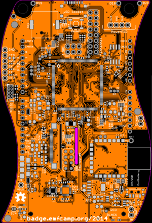
The TiLDA MKe project, Code name "ElectroMagnetic Boogaloo", is being headed by 'RepRap' Matt and Bob
Aim
The main aim of the 2014 badge is to give camp attendees live schedule updates and notifications. As with the original TiLDA we wanted to keep with an Arduino compatible platform that will allow badge hacking during and after the camp. As with previous badge all code and design files are available.
Features and Functions
Essential
The following are considers core things that the badge must do for EMF2014
- Receive and display announcements on talks scheduling
- user registers their lanyard and which talks/workshops they are interested in on the emf web site
- lanyard’s registered for talks receives reminders and notice of when and where a talk will be especially important if a talk is moved (time/location)
- Torch Mode
- One of the side effect of the two RGB LED's on TiLDA was they made a great torch
- Arduino Compatible
- Work during the event and be useful afterwards
Hardware
The following hardware has been included on the badge.
- Atmel ATSAM3X8E
- This is the same chip as the Arduino Due and gives us the base platform for the badge
- 32bit ARM Cortex M3 * 84MHz
- 512KBytes Flash RAM
- 96KBytes of SRAM
- A 128x64 pixel monochrome LCD display
- Ciseco SRF Radio
- 868Mhz RF Transceiver
- Simple UART interface
- Low power sleep mode
- MPU-6050 3-axis Accelerometer and 3-axis gyro
- I2C interface
- Tri-Axis angular rate sensor (gyro) with a sensitivity up to 131 LSBs/dps and a full-scale range of ±250, ±500, ±1000, and ±2000dps
- Tri-Axis accelerometer with a programmable full scale range of ±2g, ±4g, ±8g and ±16g
- Digital Motion Processing™ (DMP™) engine offloads complex MotionFusion, sensor timing synchronization and gesture detection
- PMIC & LiPo
- Joystick
- Buttons
- RGB LED's
- IR
- Arduino Headers
- Pads for wearable tech
Hacking
To use our board definition you will need to first get the Arduino 1.5.7 IDE from here
Next you can download the TiLDA Mk2 Firmware project from either the github repo or via direct download
Now copy the "hardware" folder to your Sketchbook folder, this is usually ~/Sketchbook/
Start the Arduino IDE and your will be able to select TiLDA Mk2 for the Tools->Board menu
Source
All the source code and designs are on openly available on Github:
- Hardware - the full board design
- Documentation - a dump of relevant parts datasheets
- Firmware - source code for the badge software
- Software - server-side software for the network

